Tang Nano 9k Softcore Blink, Merging Method
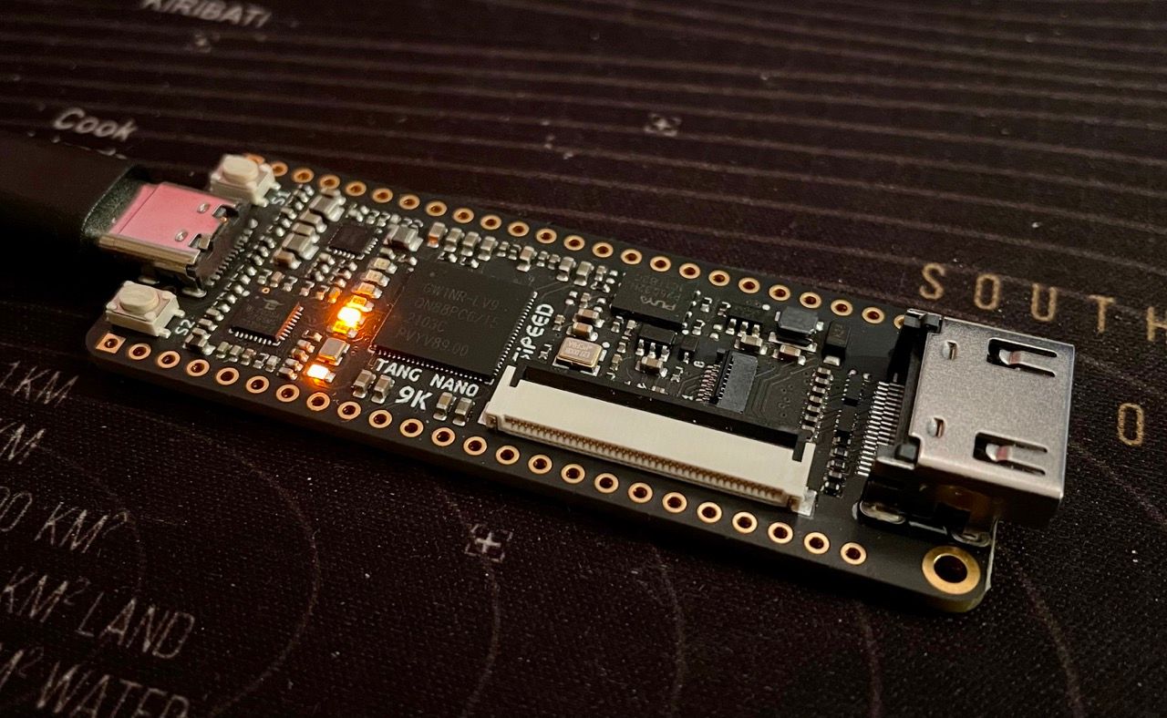
Hey and welcome to my first Tutorial Blog post. The goal is to Blink the LEDs via an integrated soft core Processor. In this part, we do that by combining the Hardware Design and the MCU program and flashing the packet to the SRAM of the Tang Nano 9k.
https://blog.ruux.de/tang-nano-9k-softcore-blink-user-flash-method/
Tools that you need
- Hardware
- Tang Nano 9k
- Computer with Winwows or Linux
- Software
- Gowin EDA [1]
- Gowin MCU Designer [1]
- EMPU M1 SDK Download
- The Schematic of the Tang Nano 9k Download
[1] You may need to aply for a free licence Here
Step 1: Software
We Start with the GOWIN MCU Designer (GMD) and create there a new C Project.
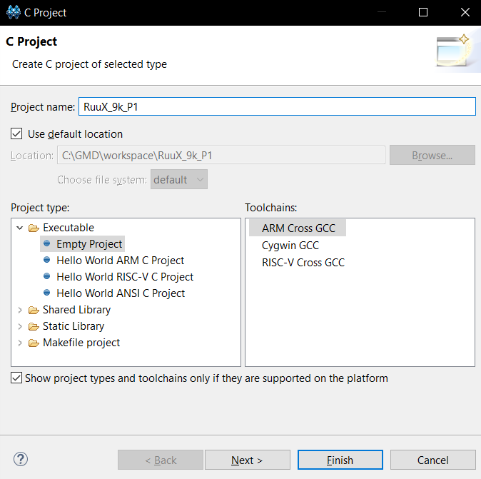
We give it a name and choose the Empty Project as the type and the ARM Cross GCC as the Toolchain. Click Next and Next and then select the "arm-none-eabi-gcc" as the Toolchain. Finally, click finish.
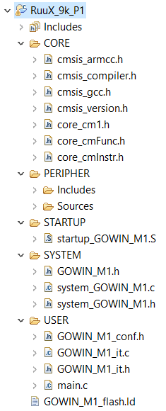
Create 5 new Folders in the main directory: CORE, PERIPHER, STARTUP, SYSTEM and USER.
Now we copy the relevant files from the Downloaded SDK inside those folders
- SDK\src\c_lib\lib\CMSIS\CoreSupport\gmd -> CORE
- SDK\src\c_lib\lib\StdPeriph_Driver -> PERIPHER
- SDK\src\c_lib\lib\CMSIS\DeviceSupport\startup\gmd -> STARTUP
- SDK\src\c_lib\lib\CMSIS\DeviceSupport\system -> SYSTEM
- SDK\src\c_lib\template -> USER
- SDK\src\c_lib\lib\Script\flash\gmd -> Main Dir
So, my Folder Structure Looks now like this:
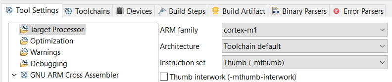
Next We need to Config the Build Settings. For this, navigate to the Properties of the Project by right-clicking on the Project in the Project explorer. Next go to C/C++ Build > Setting. There You Should see the Tool Settings Window
In the Target processor under ARM family, choose cortex-m1.
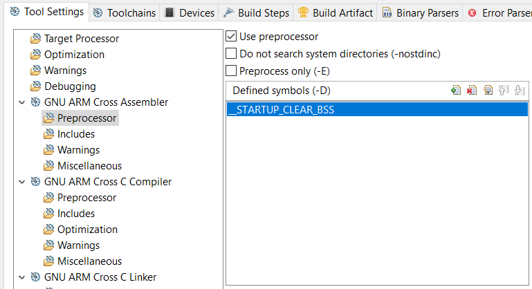
Next go to Cross ARM GNU Assembler > Preprocessor > Defined symbols (-D) and add "__STARTUP_CLEAR_BSS"#
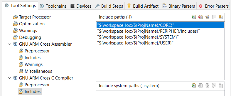
Next Select Cross ARM C Compiler > Includes > Include paths (-I) and add there
"${workspace_loc:/${ProjName}/CORE}" "${workspace_loc:/${ProjName}/PERIPHERAL/Includes}" "${workspace_loc:/${ProjName}/SYSTEM}" "${workspace_loc:/${ProjName}/USER}"
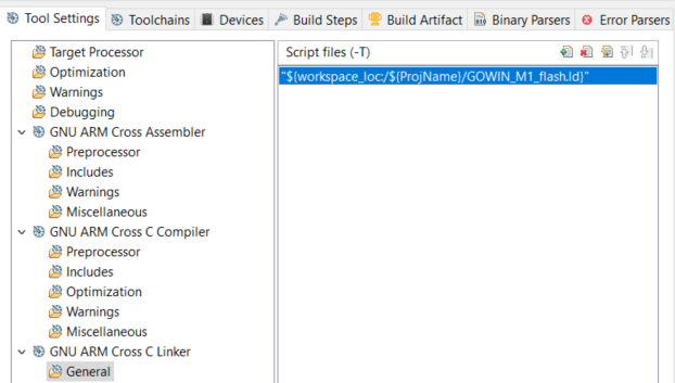
Now go to Cross ARM C Linker > General > Script files (-T) and add there the linker script in the main directory
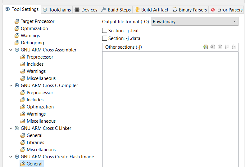
Finally, in the Tool Setting Tab, go to Cross ARM GNU Create Flash Image > General > Output file format (-O) ad select there Raw Binary
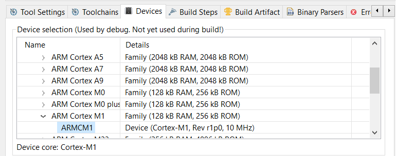
As a last step, we need to select the device. For that, we need to go into the Devices Tab. There we can select under Devices the ARMCM1
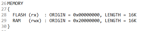
Click now Ok and open the GOWIN_M1_flash.ld file. There we have to change under Memory the Flash and RAM Size to 16k.
Code
Next We are going to change the main.c file under templates. I copied the code from the examples of the SDK, and changed it, so it can use all 6 LEDs on the board
/*
 * *****************************************************************************************
 *
 * 		Copyright (C) 2014-2021 Gowin Semiconductor Technology Co.,Ltd.
 *
 * @file			main.c
 * @author		Embedded Development Team
 * @version		V1.6.1
 * @date			2021-01-01 09:00:00
 * @brief			Main function.
 ******************************************************************************************
 */

/* Includes ------------------------------------------------------------------*/
#include "GOWIN_M1.h"

/* Declarations ------------------------------------------------------------------*/
void GPIOInit(void);
void delay(__IO uint32_t nCount);

int main(void)
{
	SystemInit();	//Initializes system clock
	GPIOInit();		//Initializes GPIO0

	while(1)
	{
		GPIO_WriteBits(GPIO0,0xFE);
		delay(1333000);

		GPIO_WriteBits(GPIO0,0xFD);
		delay(1333000);

		GPIO_WriteBits(GPIO0,0xFB);
		delay(1333000);

		GPIO_WriteBits(GPIO0,0xF7);
		delay(1333000);

		GPIO_WriteBits(GPIO0,0xEF);
		delay(1333000);

		GPIO_WriteBits(GPIO0,0xDF);
		delay(1333000);
	}
}

//Initialize GPIO
void GPIOInit(void)
{
	GPIO_InitTypeDef GPIO_InitType;

	GPIO_InitType.GPIO_Pin = GPIO_Pin_0 |
	                         GPIO_Pin_1 |
	                         GPIO_Pin_2 |
	                         GPIO_Pin_3 |
	                         GPIO_Pin_4 |
	                         GPIO_Pin_5;
	GPIO_InitType.GPIO_Mode = GPIO_Mode_OUT;
	GPIO_InitType.GPIO_Int = GPIO_Int_Disable;

	GPIO_Init(GPIO0,&GPIO_InitType);

  GPIO_WriteBits(GPIO0,0xF);//light : low level
}

//delay
void delay(__IO uint32_t nCount)
{
	for(; nCount != 0; nCount--);
}
Cross two fingers and build the project.
Preparing the software Design for merging with the Hardware
For that, we need the make_hex tool located under SDK\tool\make_hex\bin
Simply open PowerShell and navigate to the same folder where the tool is located via the cd command. Execute the tool with location of the bin file found in the debug folder of the GMD project as a parameter. You should now have 4 itcm files in this directory.
Step 2: Hardware
As a next step, we need to create the hardware with the GOWIN FPGA Designer First create a new project and give it a name. Next, select GW1NR-LV9QN88PC6/I5 as the Device. As a tip: you can get all Device names in one table here
Click Next and Finish
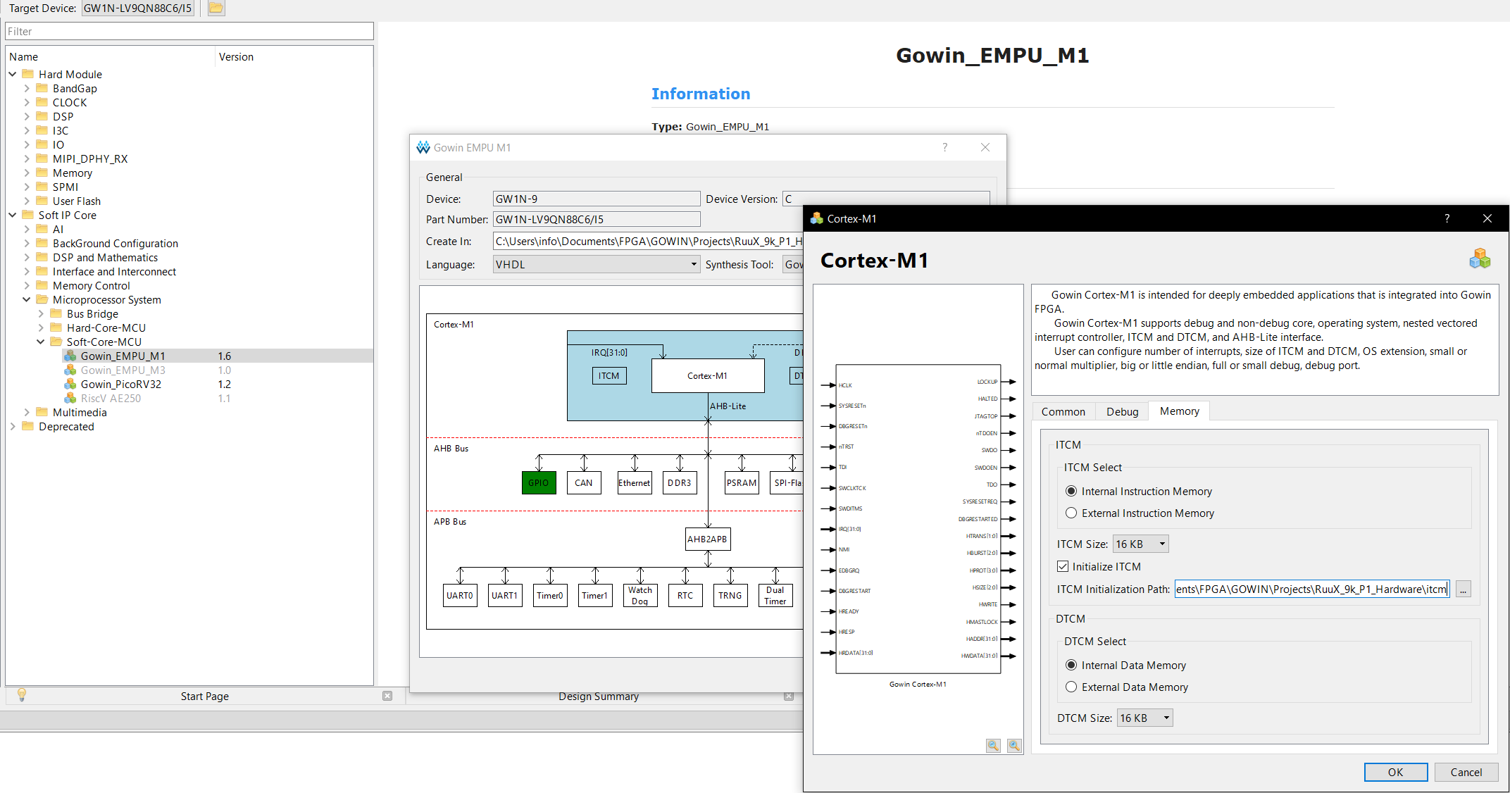
Next, we instantiate the soft core. For that, open the IP Core Generator. Under Soft IP Core > Microprocessor System > Soft-Core-MCU, you can find the Gowin_EMPU_M1. Click on it to open the configuration window. Double-click on the Cortex-M1 Rectangle in the Middle to configure it. Uncheck the Enable Debug checkbox under the Debug Tab. Next, Enable Initialize ITCM under the Memory tab. Click on the ... Button and create a new Directory with the name itcm and select it. Don't forget to copy the generated itcm files in the new created folder. Click ok to close the window. Next, Enable the GPIO by double-clicking the GPIO Rectangle and check the Enable GPIO checkbox. Click Ok. For the Language, I choose VHDL, but you can choose whatever Language you want. Click ok to generate the IP Core. Click yes to add the new generated files to the project.
Go to the Process Tab on the left and click Synthesize. Next, Open the Floor Planer.
Now assign the in outs to the corresponding pins with the help of the previously downloaded Schematic.
So in our case
HCLK → 52
hwRstn → 4
GPIO[0] → 10
GPIO[1] → 11
GPIO[2] → 13
GPIO[3] → 14
GPIO[4] → 15
GPIO[5] → 16
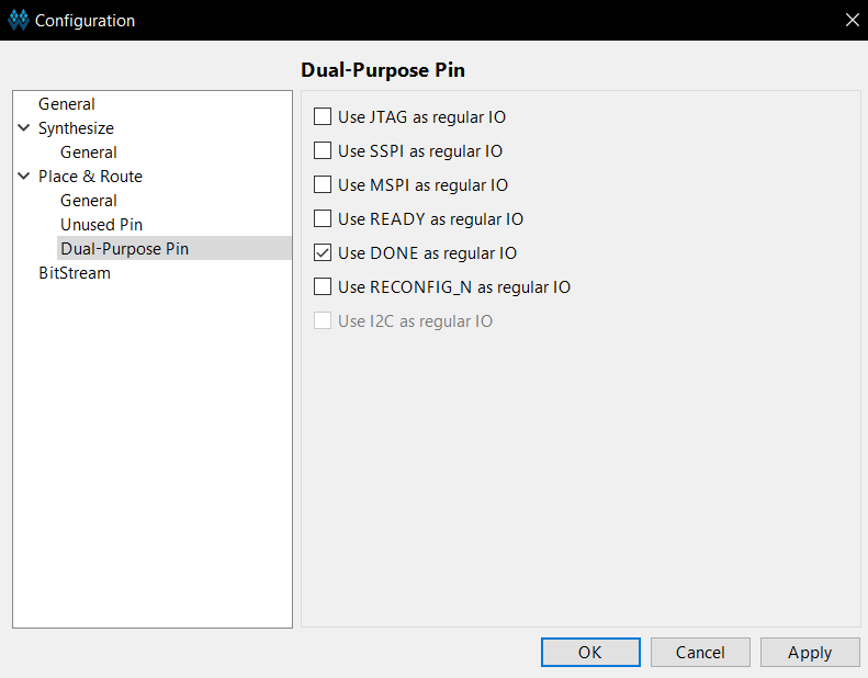
To Use the first LED go to Project ⇾ Configuration ⇾ Place & Route and then check Use DONE as regular IO
Run Place & Route, cross again your fingers (this time harder) and upload it to your Board. Hopefully, you should now see this:
If you got stuck at a point, you can download my project Files Here
Credit:
I want to give credit to Dhia Zerrari verilog-indeed who created a Tutorial for the Tang Nano 4k.
Documentation:
For further information, i can recommend reading the following documentations given by GOWIN
- IPUG532-1.9E_Gowin_EMPU_M1 Download Reference Manual
- IPUG533-1.7E_Gowin_EMPU_M1 Software Programming Reference Manual
- IPUG536-1.8E_Gowin_EMPU_M1 IDE Software Reference Manual
- IPUG531-1.9E_Gowin_EMPU_M1 Hardware Design Reference Manual
What's Next ?
Next, I want to utilize the User Flash integrated into the Tang Nano 9k to upload the sketch there, so uploading is way easier and quicker.
If you have already done this, don't hesitate to write a comment or email me :)
Until then I wish you a pleasant day
See u ^^