Tang Nano 9k Softcore Blink, Fast Method
Hey everyone :)
This is a quick follow up on the previous Tutorial. As you may have noticed, changing the program is a bit difficult. So, I discovered how to use the User Flash to use it as the Flash for the Soft core MCU. But on the downside, I only found the example and the mandatory User flash controller was only written in Verilog, so I have to stick to the example here. Maybe when I get more information how to generate this User flash controller, I revisit this Tutorial. But because this makes the life a lot easier, I don't want to withhold this method.
Generate the bin file is Mandatory to continue, so please ensure you read the step one of my previous Tutorial. You could also download the finished GMD Project and extract the bin file from there if you are lazy or just want to find out how this method works
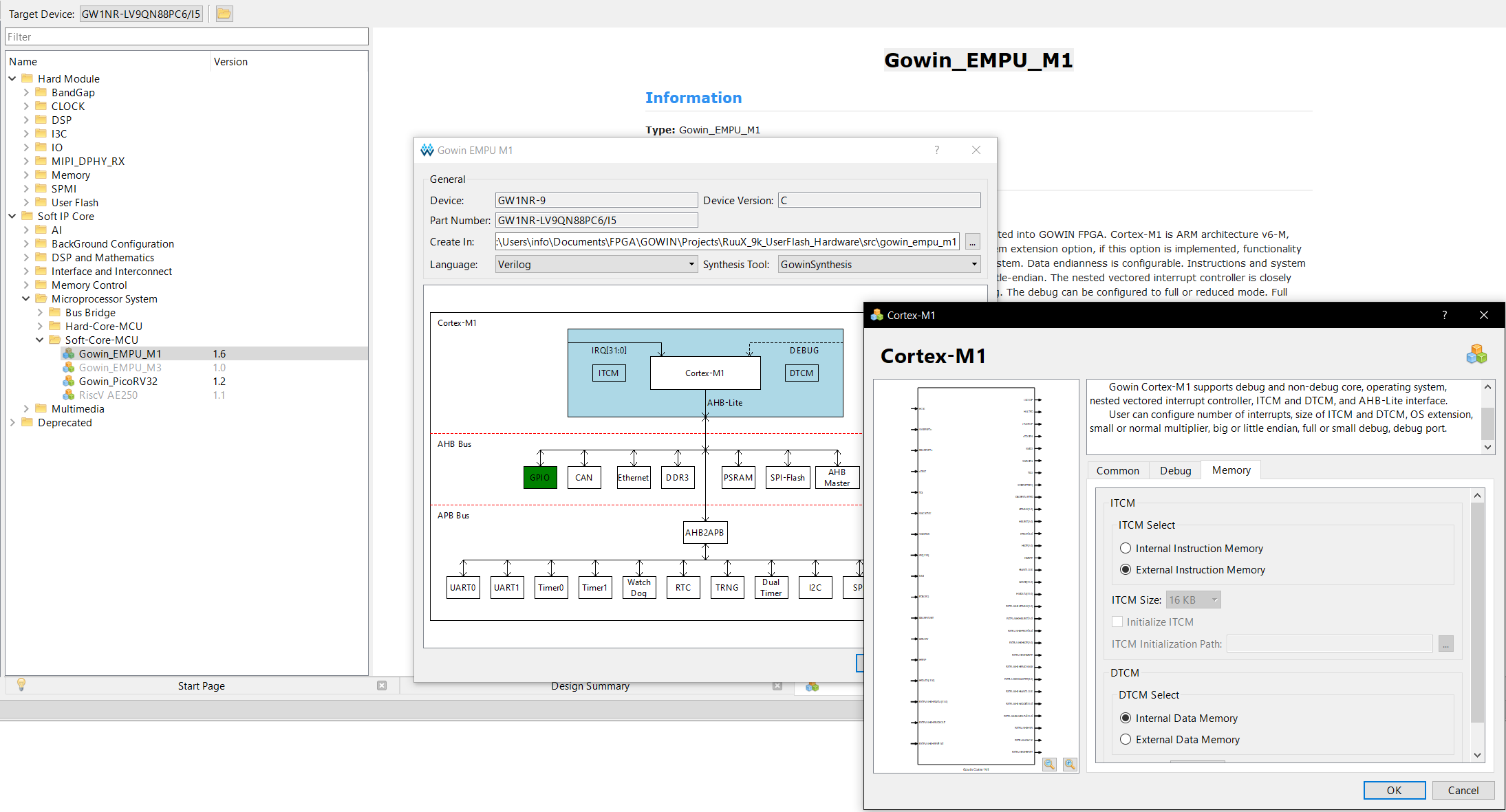
We start again with creating a new project and select the GW1NR-LV9QN88PC6/I5 as our device.
Next, we create the mandatory IPs:
Start with the EMPU M1 by clicking on the IP Core Generator and pick the Gowin_EMPU_M1 from the list. Click on the Cortex M1 Rectangle, disable the Debug ports, and select External Instruction Memory under the Memory→ITCM
Finally enable the GPIO Ports. Leave the language on Verilog and click OK and click yes, so the files are added to the project.
As said for this Tutorial, I have no other choice as to use the Verilog language because we have to copy the User flash controller from the example project in our example folder. So copy the SDK\ref_design\FPGA_RefDesign\gowin_empu_m1\src\userflash_controller into the src folder of our project.
Add this file by right-clicking in the Design Window on the left and click on Add Files and select the userflash_controller.v we just copied.
Next, we create the rPLL Module with the following parameters:
CLKIN 27 and CLKOUT to 54 to double the clock signal.
Click again OK and add and yes.

Finally, create a top.v file and copy the following Verilog code, I mostly copied from the example project given in the SDK.
`resetall

module Gowin_EMPU_M1_template (
  LED,
  HCLK,		    //System Clock
  hwRstn	    //System Reset
);

input HCLK;     // System clock
input hwRstn;   // System reset

//GPIO
output [5:0] LED;

wire MCLK;          //mcu clock

//pll
Gowin_rPLL u_Gowin_rPLL
(
  .clkout(MCLK),    //output clkout 20MHz
  .clkin(HCLK)      //input clkin 50MHz
);

wire [31:0] EXTFLASH0HRDATA;
wire EXTFLASH0HREADYOUT;
wire [1:0] EXTFLASH0HRESP;
wire [1:0] EXTFLASH0HTRANS;
wire [2:0] EXTFLASH0HBURST;
wire [3:0] EXTFLASH0HPROT;
wire [2:0] EXTFLASH0HSIZE;
wire EXTFLASH0HWRITE;
wire EXTFLASH0HREADYMUX;
wire [3:0] EXTFLASH0HMASTER;
wire EXTFLASH0HMASTLOCK;
wire [31:0] EXTFLASH0HADDR;
wire [31:0] EXTFLASH0HWDATA;
wire EXTFLASH0HSEL;
wire EXTFLASH0HCLK;
wire EXTFLASH0HRESET;

//userflash controller
GW_FLASH u_GW_FLASH (
    .hclk                   (EXTFLASH0HCLK),
    .hresetn                (EXTFLASH0HRESET),
    .targflash0_hsel_i      (EXTFLASH0HSEL),
    .targflash0_haddr_i     (EXTFLASH0HADDR),
    .targflash0_htrans_i    (EXTFLASH0HTRANS),
    .targflash0_hwrite_i    (EXTFLASH0HWRITE),
    .targflash0_hsize_i     (EXTFLASH0HSIZE),
    .targflash0_hburst_i    (EXTFLASH0HBURST),
    .targflash0_hprot_i     (EXTFLASH0HPROT),
    .targflash0_memattr_i   (2'b00),
    .targflash0_exreq_i     (1'b0),
    .targflash0_hmaster_i   (EXTFLASH0HMASTER),
    .targflash0_hwdata_i    (EXTFLASH0HWDATA),
    .targflash0_hmastlock_i (EXTFLASH0HMASTLOCK),
    .targflash0_hreadymux_i (EXTFLASH0HREADYMUX),
    .targflash0_hauser_i    (1'b0),
    .targflash0_hwuser_i    (4'b0000),
    .targflash0_hrdata_o    (EXTFLASH0HRDATA),
    .targflash0_hreadyout_o (EXTFLASH0HREADYOUT),
    .targflash0_hresp_o     (EXTFLASH0HRESP),
    .targflash0_exresp_o    (),
    .targflash0_hruser_o    (),
    .flash_err_o            (),    // Flash memory/System error
    .flash_int_o            (),    // EFlash interrupt
    .pclk                   (EXTFLASH0HCLK),
    .pclkg                  (EXTFLASH0HCLK)
);

//gowin empu m1
Gowin_EMPU_M1_Top u_Gowin_EMPU_M1_Top (
  .LOCKUP(),
  .GPIO(LED),
  .EXTFLASH0HRDATA(EXTFLASH0HRDATA), //input [31:0] EXTFLASH0HRDATA
  .EXTFLASH0HREADYOUT(EXTFLASH0HREADYOUT), //input EXTFLASH0HREADYOUT
  .EXTFLASH0HRESP(EXTFLASH0HRESP), //input [1:0] EXTFLASH0HRESP
  .EXTFLASH0HTRANS(EXTFLASH0HTRANS), //output [1:0] EXTFLASH0HTRANS
  .EXTFLASH0HBURST(EXTFLASH0HBURST), //output [2:0] EXTFLASH0HBURST
  .EXTFLASH0HPROT(EXTFLASH0HPROT), //output [3:0] EXTFLASH0HPROT
  .EXTFLASH0HSIZE(EXTFLASH0HSIZE), //output [2:0] EXTFLASH0HSIZE
  .EXTFLASH0HWRITE(EXTFLASH0HWRITE), //output EXTFLASH0HWRITE
  .EXTFLASH0HREADYMUX(EXTFLASH0HREADYMUX), //output EXTFLASH0HREADYMUX
  .EXTFLASH0HMASTER(EXTFLASH0HMASTER), //output [3:0] EXTFLASH0HMASTER
  .EXTFLASH0HMASTLOCK(EXTFLASH0HMASTLOCK), //output EXTFLASH0HMASTLOCK
  .EXTFLASH0HADDR(EXTFLASH0HADDR), //output [31:0] EXTFLASH0HADDR
  .EXTFLASH0HWDATA(EXTFLASH0HWDATA), //output [31:0] EXTFLASH0HWDATA
  .EXTFLASH0HSEL(EXTFLASH0HSEL), //output EXTFLASH0HSEL
  .EXTFLASH0HCLK(EXTFLASH0HCLK), //output EXTFLASH0HCLK
  .EXTFLASH0HRESET(EXTFLASH0HRESET), //output EXTFLASH0HRESET
  .HCLK(MCLK),	    //System Clock
  .hwRstn(hwRstn)	//System Reset
);

endmodule
Click on the Synthesis Button, so we can continue with the Floor Planer:
HCLK→52
hwRstn→4
LED[0]→10
LED[1]→11
LED[2]→13
LED[3]→14
LED[4]→15
LED[6]→16
Click Save and run Place & Route
Now Click Program device, Save and double-click on SRAM Program. Select MCU Mode L under Access Mode and Firmware Erase, Program. Leave the .fs file as it is and select the bin file under the DEBUG folder of the GMD project we created in the last tutorial.
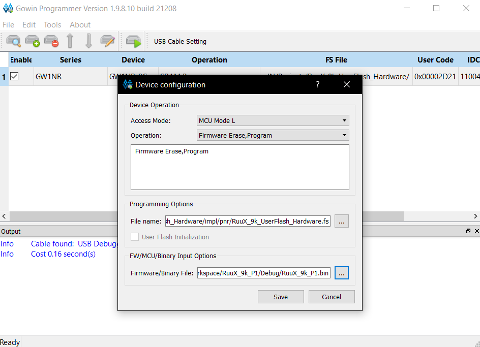
Click Save and click on the Program/Configure to upload the Hard and Software Design.
You should now see again a blinking Tang Nano 9k :)
Here you can download the Project.