FPGA Microphone Array: Part 1 Hardware
Hi there,
Long time no see, but I'm back with a new project: An ultrasonic microphone array running on a PYNQ FPGA. Additionally, I tried to make an Ultrasonic Phase Array, but spoilers: it didn't work well, so I'm just going to go briefly over this topic.
In this part, I want to cover the goals of the project and the hardware I came up with.
Goals
A little bit over a year ago, one of my favorite YouTubers, Bitluni, released two videos about phase arrays. In the first video, he explains the principle of a phase array and builds it successfully. The phase array was able to send sound in a specified direction without the need for moving parts. A microphone receives the signal reflected from an object. With the information about the Steering Angle of the phase array and the time the signal took to travel to the object and back He was capable of creating a Picture of the environment in front of the sensor, just like a Radar screen. However, he observed that the speed of the scanning was slow due to the time the sound took to travel to the object and back. So a scan with 64 angles and a scanning depth of 1.6 meters would result in a scanning period of
\[ time = n_{angles} \cdot \frac{dist\cdot2}{v_{sound}} = 64 \cdot \frac{1.6m\cdot2}{343\frac{m}{s}} \approx 0.3 s\]
per scan. To achieve faster scanning, it is possible to turn the working principle of a phase array around and send one pulse out and receive with a microphone array the incoming waves. With the information from each microphone, it is possible to determine the distance and angle relative to the ultrasonic transmitter. Because he did not finish the project (as of 12.23), I took the opportunity and built one on my own. But because I was eager to learn more about FPGAs, I decided to use one for my project. Precisely, a Xilinx FPGA from Diligent: the PYNQ board. I mainly chose Xilinx over GOWIN because the Software Vivado is just better for more complex designs, and the FPGA comes with more Block RAM and DRAM, which will be useful in the future. To have more freedom, I decided to build an emitter module with 8 Ultrasonic speakers and a receiving module with 8 Ultrasonic Receivers.
Milestones
The following part will provide an overview of the project's progress. Each milestone will be covered by one or more separate blog articles.
-
Distance Measurement (DONE)
To make a "normal" distance measurement, the emitter module has to be driven by the FPGA to make the pulses. One of the receiving microphones requires sampling, saving, and processing of the data. -
Detecting Objects with the Phase array (DONE but did not work well)
With the change in the steering angle of the Phase Array combined with the distance measurement from above, it should be possible to create a 2D map of the environment. -
Detecting the angle of one object (DONE)
The goal of this milestone will be to detect the angle of one object by measuring the time difference of arrival (TDOA) of two microphones. -
Detecting multiple objects (IDEA)
This is, at the time I am writing this article, only an idea, so I cannot guarantee if it works. The Plan is to use an Algorithm like MUSIC
The Hardware
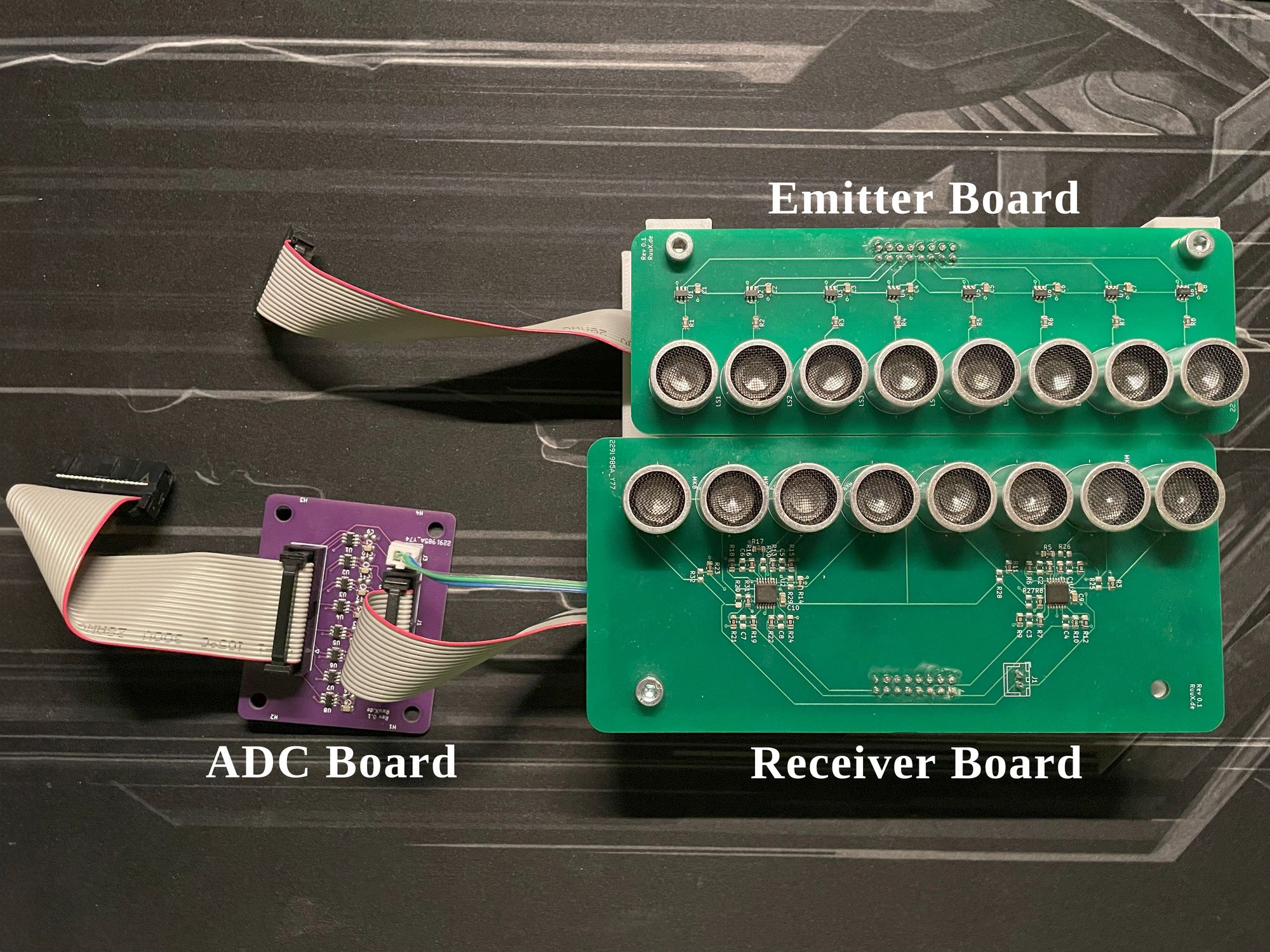
The design of the hardware is somewhat inspired by the design of Bitluni, but it is adapted to the FPGA. It consists of four different PCBs.
- Emitter board: consists of eight ultrasonic transmitters with drivers. It is connected to the Connector board directly.
- Receiving board: consists of eight microphones and eight Op-Amps for amplification. It is connected to the ADC Board.
- ADC board: with seven MAX11116 (8-bit) and one MAX11105 (12-bit) ADC converters. The 12-bit ADC is just there for more freedom with experimentation and was intended for use with the phase array.
- Connector board: has no active or passive components. It just connects the two ribbon cables to the IO of the PYNQ FPGA.
Emitter Board
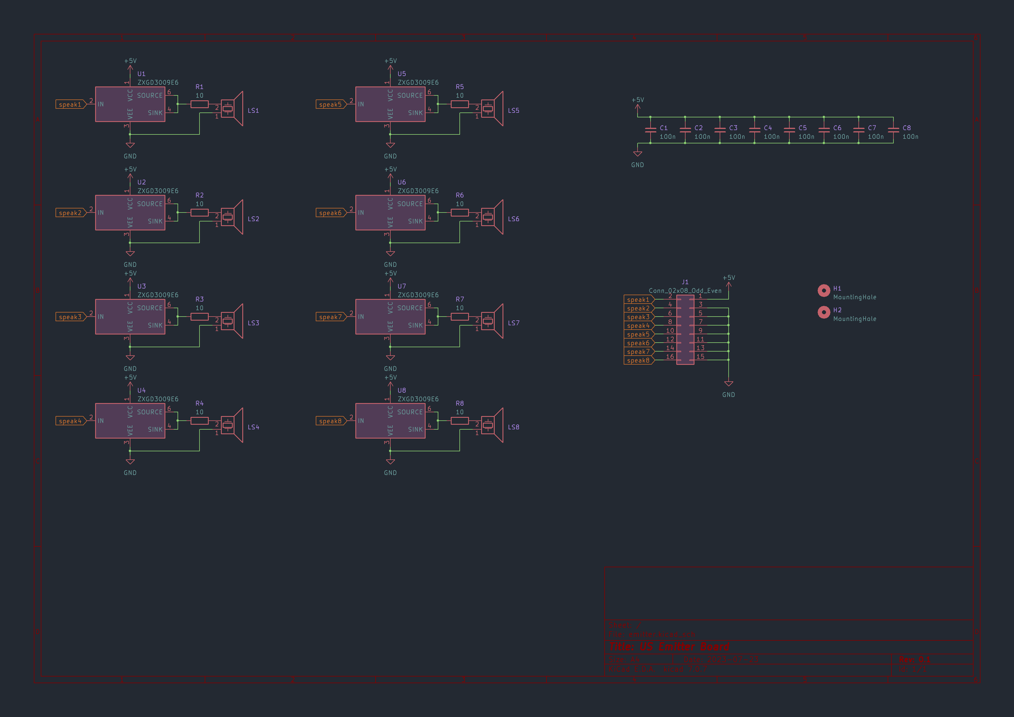
The emitter board consists of eight single-gate drivers that are utilized to drive the microphones. My choice fell on the ZXGD3009E6 due to its low-cost and high availability, so there is really nothing special about them.
Receiving Board
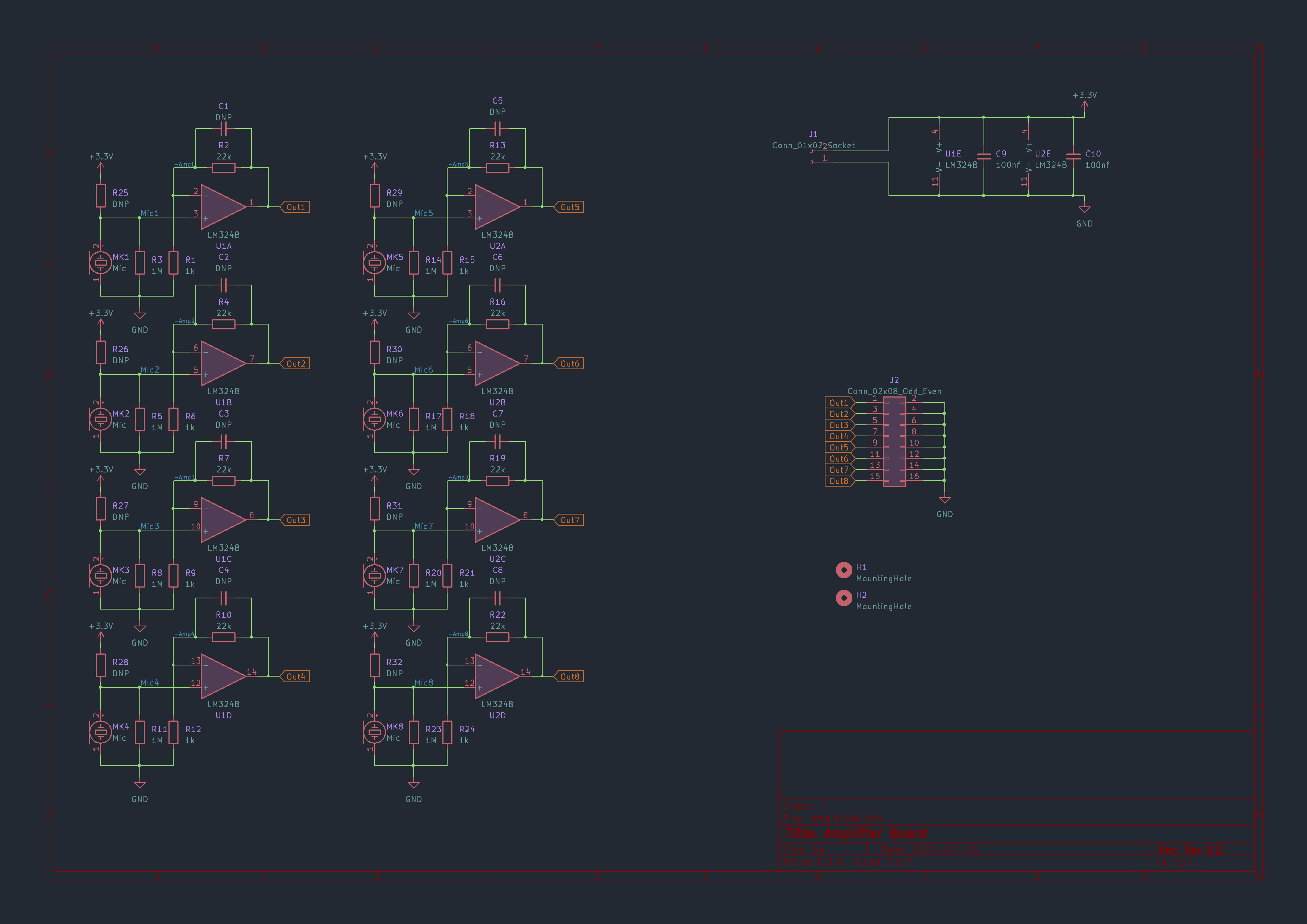
In my initial experiment, I transmitted an ultrasonic pulse against my ceiling using a square wave signal ranging from 0 to 5 volts. Then I measured the incoming wave with an oscilloscope. The Amplitude was roughly 10 mV, way too little to make a good distinction between the nose and my ultrasonic signal. To keep the cost low, I decided to use 8-bit ADCs driven by 3.3V. So one Least Significant bit (LSB) equates to
\[ \frac{3,3V}{(2^8-1) LSB} \approx \frac{13mV}{LSB} \]
After some further experimentation, I opted for an amplification factor of 22. This level ensures that my signal is sufficiently detectable while maintaining a dynamic range that allows for the acceptance of stronger signals as well. With this gain, my 10 mV PP is now roughly 220 mV, which equals exactly 17 bits.
For the amplification component of my project, I chose the LM324B, a quadruple operational amplifier. This decision was based on its adequate input offset voltage and sufficient slew rate for amplifying a known frequency. A key feature of the LM324B that influenced my choice is its rail-to-rail operation on the negative supply, which was essential for my design. The affordability and high availability of this component also played a role in its selection. To eliminate the complexity of managing both negative and positive power supplies, it's necessary to shift the AC signal from the microphone, which has a minimum of 10mV, upwards. This approach streamlines the design and reduces complexity.To create the offset signal, I used the typical input bias current of 10 nA. With the 1 MΩ resistor, the 20 mV AC input signal gets an additional
\[ 10\cdot10^{-9} nA\cdot10\cdot10^6M\Omega = 10mV \]
DC offset. Additionally, there is the option to adjust the offset manually with R25–R32. Furthermore, there is also the option to add a Low pass filter when using the capacitors C1 to C8.
ADC Board
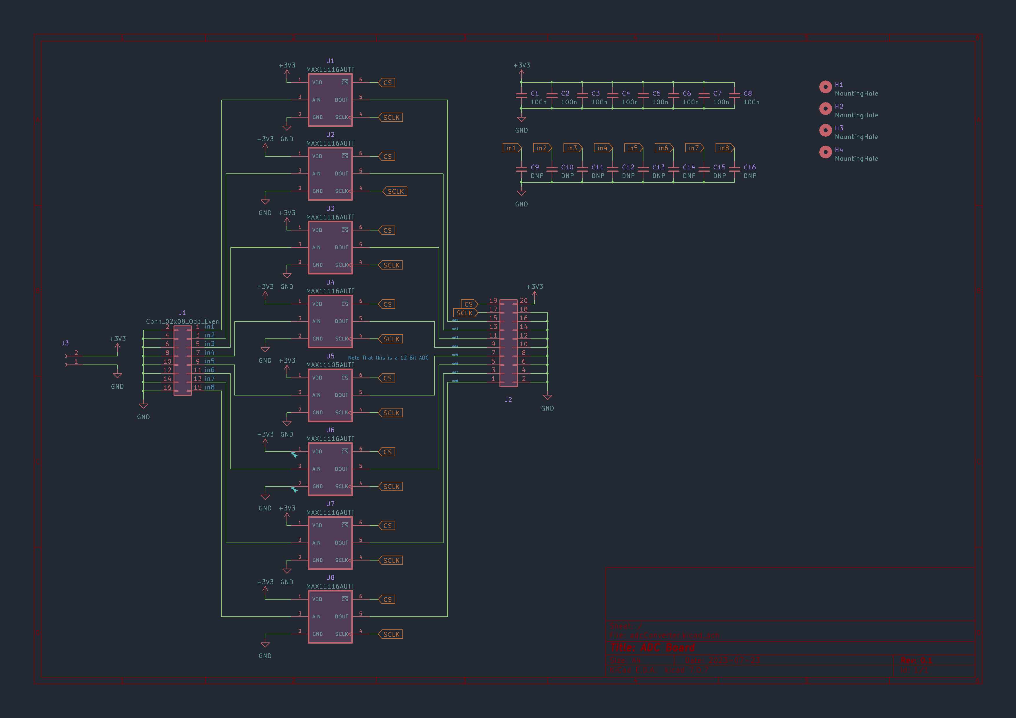
The ADC board consists of seven MAX11116, which are 8-bit @3 Msps, and one MAX11105, which is a 12-bit @2 Msps ADC. The 12-bit ADC is connected to the microphone that is placed in the center of the emitting Phase. But all in all, the 12-bit ADC is just there for more experimentation.
Additionally, there is the option to limit the frequency received by the ADC with the capacitors C9 to C16, but they were not used because the ribbon cable is a pretty good RC low-pass filter in itself.
Final
In the upcoming section of my FPGA Project Blog, I plan to dive into my FPGA Design and explain what are the necessary steps to achieve distance Measurement. Alongside this, I'm also preparing a short blog article to explore the principles of a phase array, specifically addressing the challenges I encountered and why my design didn't perform as expected. I am very excited to share my experiences and learned things I've learned. Stay tuned for a thorough exploration of these fascinating topics!