FPGA Microphone Array: Part 2 Distance Detection
This article is a presentation of an FPGA design and a demonstration of how distance measurement was achieved.
Chapter 1: Programming the Modules
Transmitter Module
There are two main modules that need to be programmed: the Transmitter module and the Receiver module.
The discussion will begin with the transmitter module. The initial plan was to create a phase array. To adjust the steering angle, it is necessary to create a phase shift between all the transmitters. To achieve this, I programmed one free running counter that shares its value with every emitter module. Each emitter module has to compare the counter value to a phase shift value it was given by the Processing System(PS). When the phase shift value is reached, the output changes. If a phase shift is greater than 180 degrees, the output is inverted. The following ASCII text explains this principle further. The advantage is that the phase shift can be changed on the fly without resetting the main counter.
                   ┌─max Val
                 ┌─┘
               ┌─┘◄Phase 180°
             ┌─┘
           ┌─┘
         ┌─┘
       ┌─┘◄Phase 0° ─┐
     ┌─┘             ├─Phase Shift
    ─┘Val 0         ─┘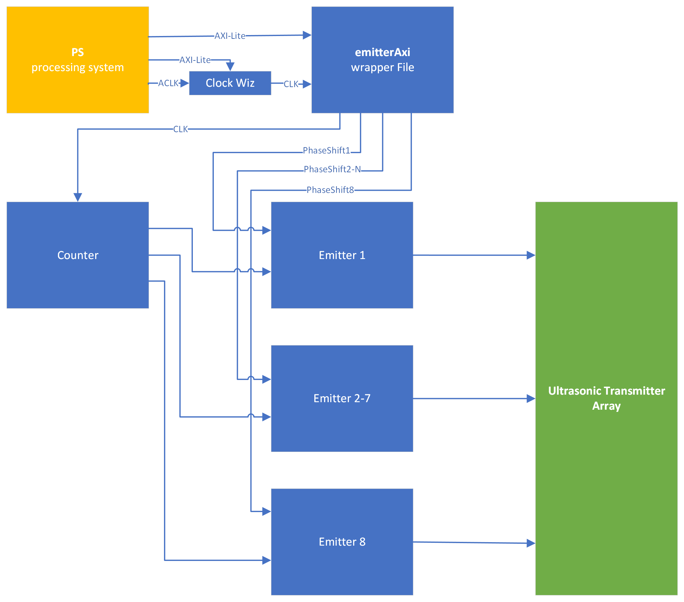
However, as mentioned in the previous blog post, the width of the beam was insufficient for accurate object detection.
Receiver Module
The receiver module is a bit more complex. The system is responsible for managing communication with the ADC modules, synchronizing data, and sending it to the FIFO for processing by the PS. The following picture shows the modules interfacing with the hardware.
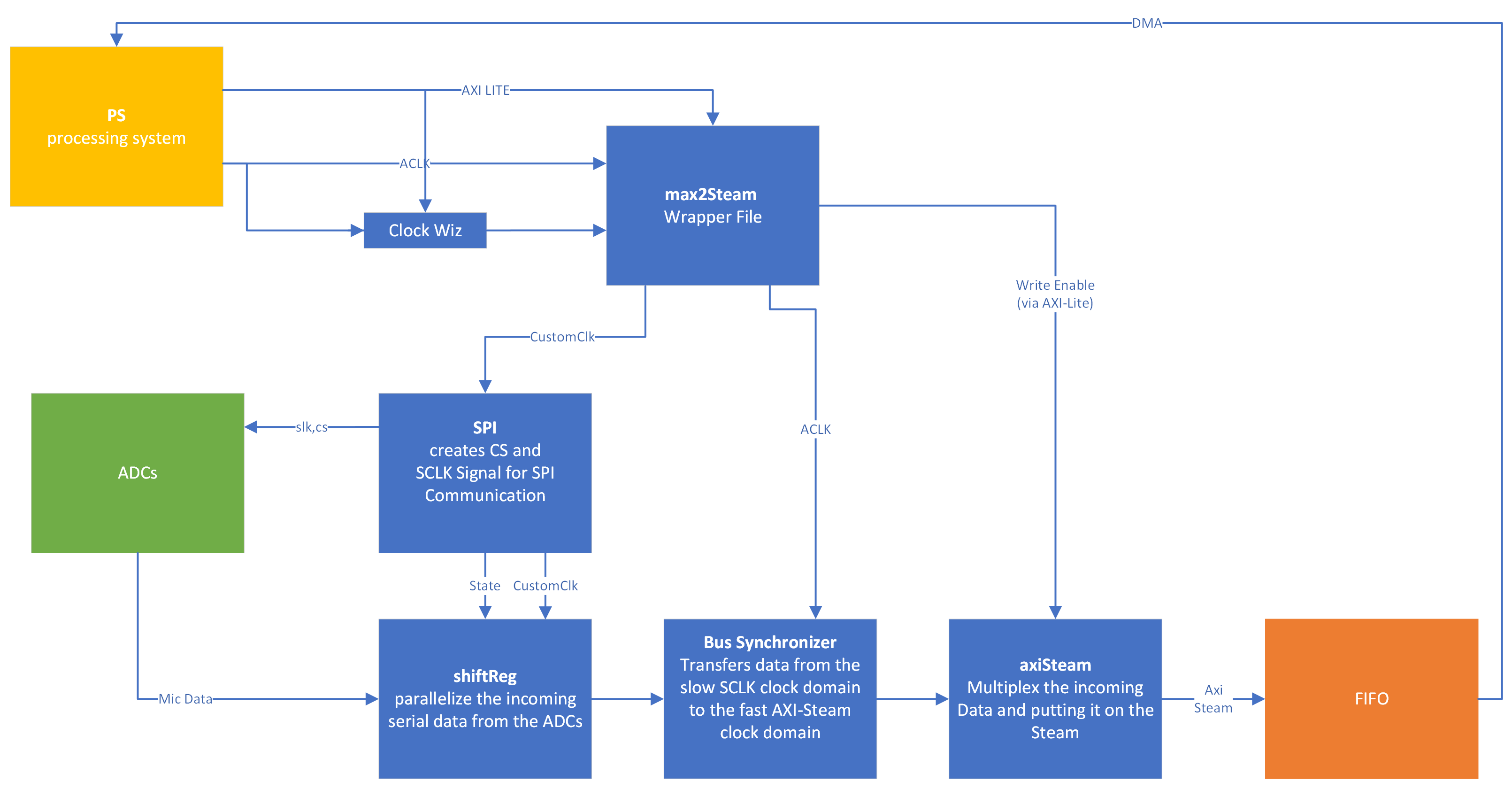
The FIFO data is feed via a Direct Memory Access (DMA) block to the RAM of the processing system.
Chapter 2: Problems
After some fiddling, the data finally reaches the PS. (Thanks to the Debug Core in Vivado). The PS could then send the data out via UART to my PC, where it was plotted with the Arduino plotter. Only one of the eight channels was in use for testing and the distance measurement.
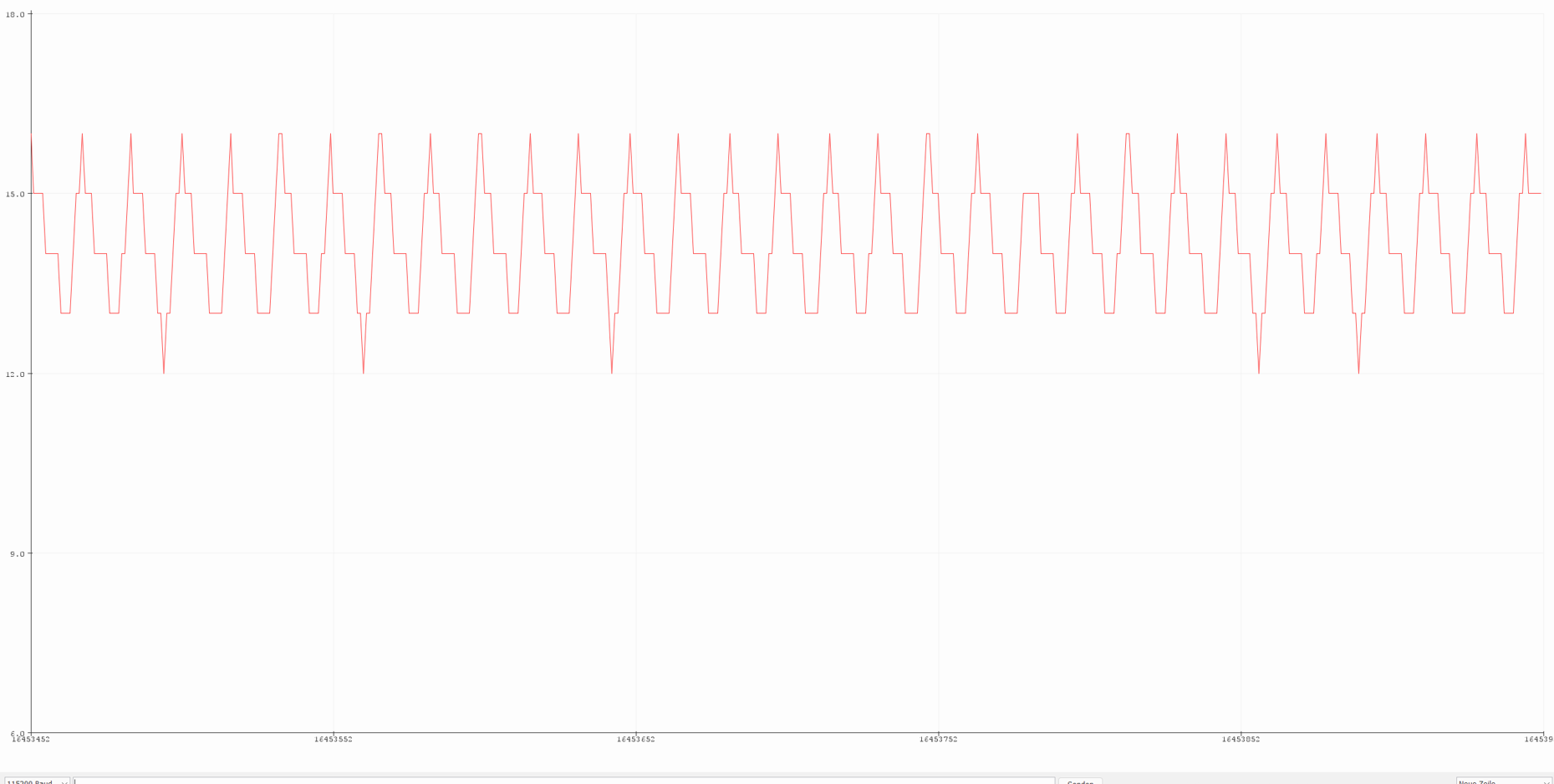
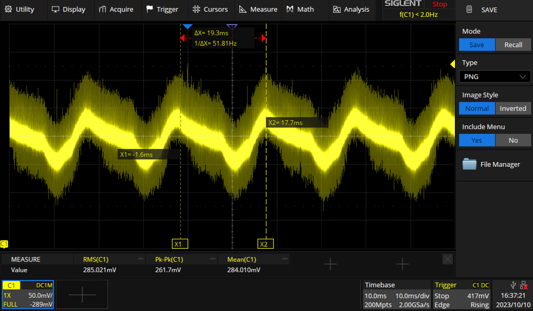
After receiving the first results, it was clear somehow the 50Hz from mains was dominant. This could be confirmed with the oscilloscope.
Chapter 3: Solutions
FIR Filter
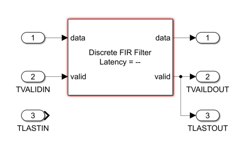
The first solution was to use a FIR Bandpass filter. To implement this, I decided to use the MATLAB HDL Coder out of curiosity.
I started with a simulation of the finished FIR filter provided by Simulink. For the input, I imported a complete FIFO dump.
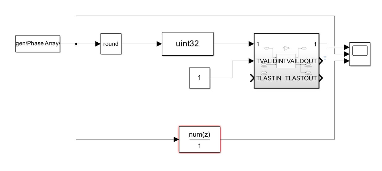
I only have images from the simulation, but the FPGA implementation worked pretty much the same.
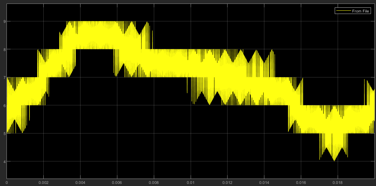
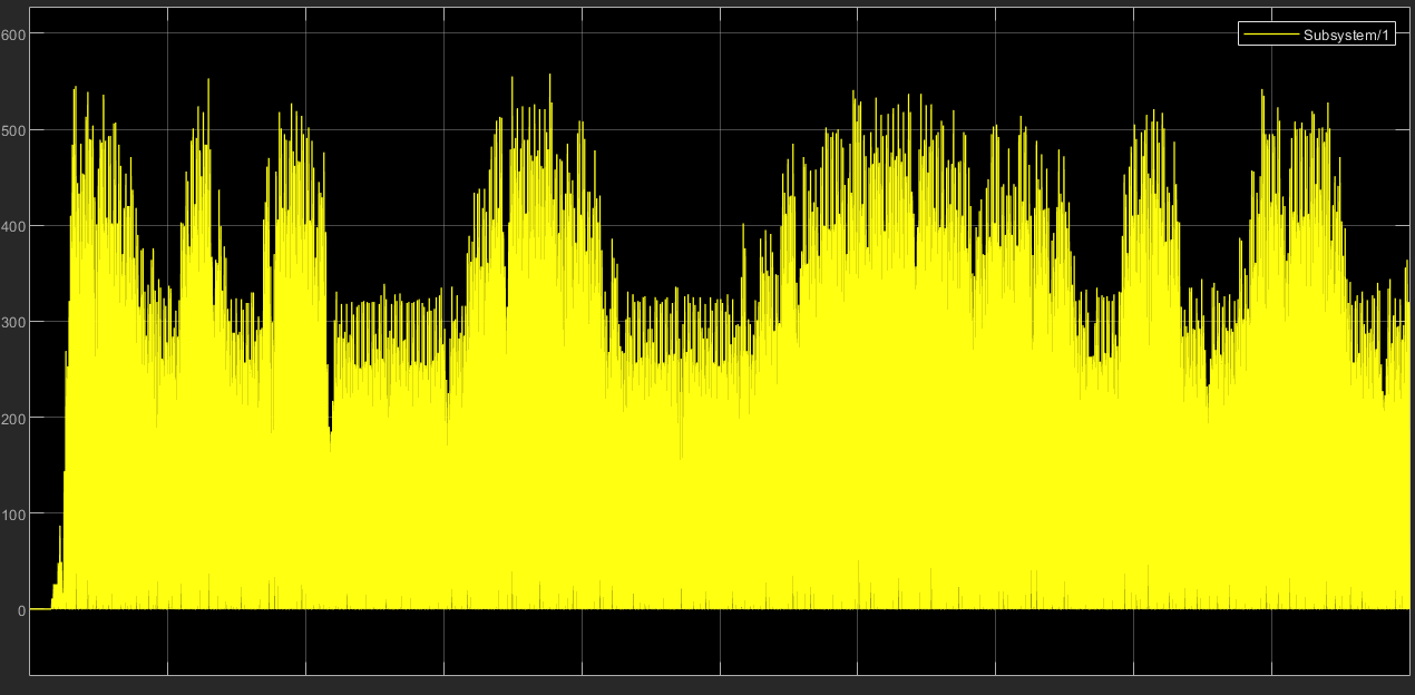
This indicates that the FIR filter has worked and the 50Hz has been eliminated :)
Cross Correlation
Because the frequency of my signal is known (40 kHz) another option to filter out the 50Hz is Cross Correlation. It's defined as \[ (x \star y)(\tau) = \int_{-\infty}^{\infty} x(t) y(t - \tau) \, dt \] Cross-correlation is like comparing two things to see how similar they are when you shift one of them. Imagine sliding one pattern over another and checking how well they match at different positions. If they match well at a certain position, you get a high value in the output, indicating similarity. The result is the filtered signal that only contains the information at 40khz.
To get the distance, I squared the signal, so I only have to deal with positive values and the reflection gets larger separated from any noise. After then, I applied a moving average filter to filter out any unwanted noise or peaks.
The path of the signal can be seen in the following screenshot. Figure 1 displays the input signal, including the pulse from the emitter, the pulse of a small object, and the reflection from the ceiling. In figure 2 you can see the 40kHz "sin" wave that is shifted over the input signal. The result of this operation is figure 3. Figure 4 shows the signal after squaring and averaging.
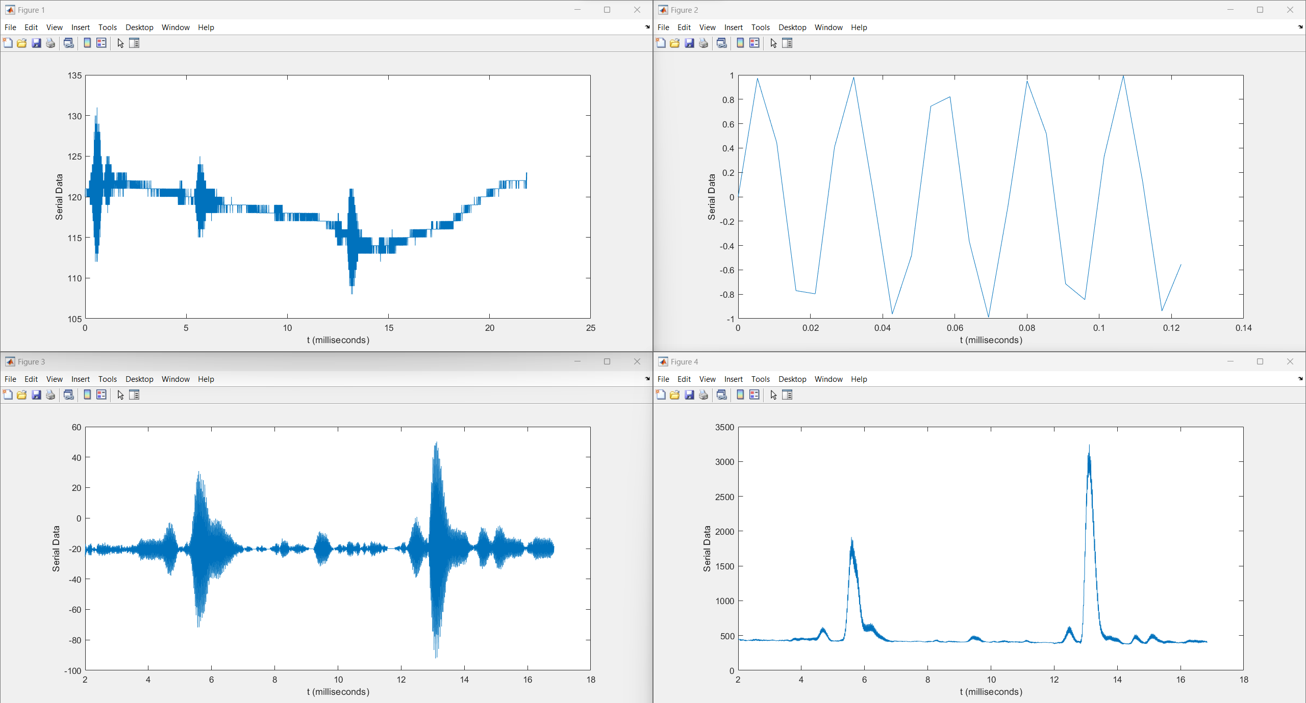
So SUCCESS I have created a very expensive ultrasonic distance sensor, and I'm proud of it.
I implemented this algorithm in the C code with the MATLAB Coder toolbox. I struggled a bit with getting the code to run on my ZYNQ processor, but after defining all data types in my MATLAB code manually, I got it to work.
Additionally, I wrote a small MATLAB GUI program to visualize the data.
The Result can be seen in this video:
Final and Lesson Learned
Lesson Learned: Don't use the MATLAB C coder. Ok, maybe a little bit exaggerated, but if you have the time it is probably better to program the algorithms yourself. The MATLAB HDL Coder, on the other hand, was straightforward to use and can save in the right application time.
The next and most likely last blog post will be about direction finding. If you have any questions or something seems unclear, hit me up. Stay safe and I wish you Happy Holidays :)